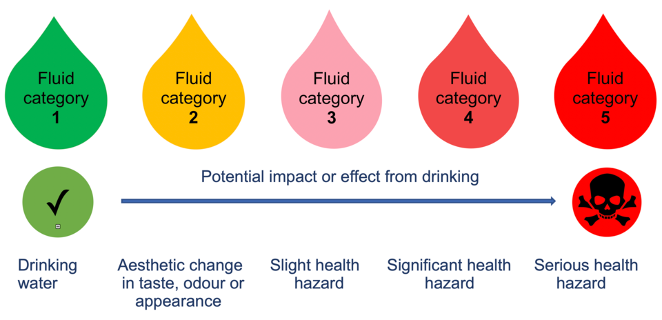
Schedule 1 of the water fittings regulations in England, Wales and Northern Ireland, byelaws in Scotland, classify the health risk posed by potential contaminants using a scale called fluid categories.
There are five fluid categories in total the lowest being 1 no risk the highest 5 a serious health hazard.
Fluid Category | Description | Example |
1
|
Wholesome (drinking) water supplied by the undertaker
|
water direct from a water undertaker’s main
|
2
|
Wholesome (drinking) water which has been changed either heated or altered in taste, odour or appearance
|
Hot water
|
3
|
Fluids posing a slight health hazard
|
low toxicity chemicals such as common disinfectants
|
4
|
Fluids posing a significant health hazard.
|
Toxic substances such as pesticides and environmental organisms
|
5
|
Fluids posing a serious health hazard
|
Pathogenic organisms, radioactive or very toxic substances such as faecal matter
|
To improve this information please give us your feedback >
Uncontrolled if downloaded. This is informative, non-statutory guidance and intended for general guidance purposes only; it is subject to change.
Compliance with this information should not be relied upon as guaranteeing no enforcement action will be taken by water undertakers. Water Regs UK accepts no liability for loss, indirect or consequential loss arising from or in connection with this guidance document.
As part of their statutory duty to enforce the water fittings regulations in England, Wales and Northern Ireland, byelaws in Scotland, the local water undertaker will identify the level of backflow protection needed. This categorisation will be based on a number of factors including the highest downstream fluid category risk the fitting is or is likely to be subject.
To improve this information please give us your feedback >
Uncontrolled if downloaded. This is informative, non-statutory guidance and intended for general guidance purposes only; it is subject to change.
Compliance with this information should not be relied upon as guaranteeing no enforcement action will be taken by water undertakers. Water Regs UK accepts no liability for loss, indirect or consequential loss arising from or in connection with this guidance document.
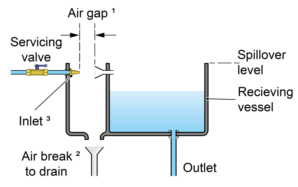
A Type AA air gap is a non-mechanical backflow prevention arrangement comprising of an inlet which discharges water into a cistern, vessel, fitting or appliance (receiving vessel) and an outlet. Depending on the outcome of an assessment by the local water undertaker it can feed a single or multiple installations.
A Type AA air gap is rated by the Regulators as suitable backflow protection against both back siphonage and back pressure at the highest level of contamination risk, fluid category 5.
A summary of some of the key requirements for a Type AA air gap is given below:
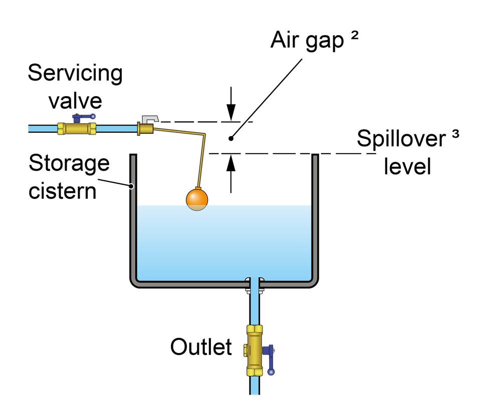
The supply pipe and inlet control must be external to the receiving vessel and fixed so the air gap is maintained and unrestricted.
The air gap is an unobstructed and complete physical break between the lowest point of discharge and the spillover level of the contents of the receiving vessel. Measured vertically it must be no less than 20 mm or twice the internal diameter of the supply whichever is the greater.
The spillover level is the level at which the contents of receiving vessel spill over the top edge when the inflow of water exceeds the outflow through the outlet i.e. demand.
The spillover is unrestricted.
If the supply pipe feeding the inlet or the inlet itself comes into contact with the contents of the receiving vessel, for example due to splashing or foaming, then the air gap is considered to be compromised and must be increased to the point no contact occurs.
Type AA air gaps should be inspected, and as necessary, maintained every 6 months (BS EN 806: 5)
To improve this information please give us your feedback >
Uncontrolled if downloaded. This is informative, non-statutory guidance and intended for general guidance purposes only; it is subject to change.
Compliance with this information should not be relied upon as guaranteeing no enforcement action will be taken by water undertakers. Water Regs UK accepts no liability for loss, indirect or consequential loss arising from or in connection with this guidance document.
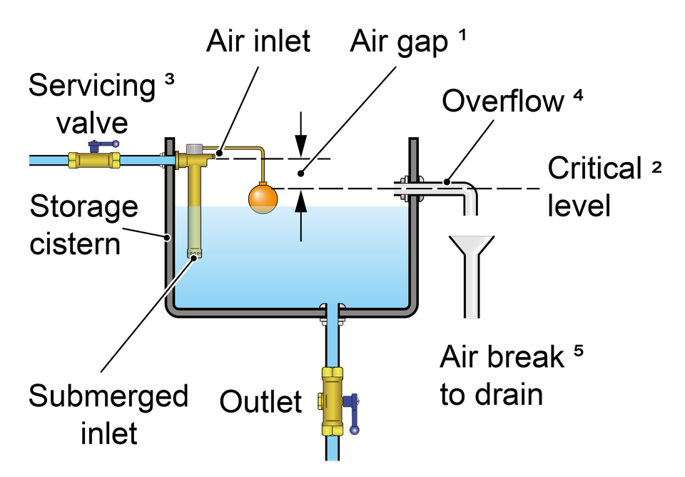
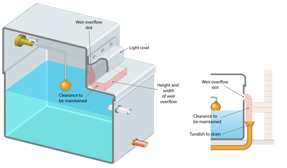
A Type AB air gap is a non-mechanical backflow prevention arrangement comprising of an inlet which discharges water into a cistern, vessel, fitting or appliance (receiving vessel) fitted with an outlet and a rectangular weir or ‘slot’ overflow. Depending on the outcome of an assessment by the local water undertaker it can feed a single or multiple installations.
A Type AB air gap is rated by the Regulators as suitable backflow protection against both back siphonage and back pressure at the highest level of contamination risk, fluid category 5.
A summary of some of the key requirements applicable to a Type AB air gap is given below:
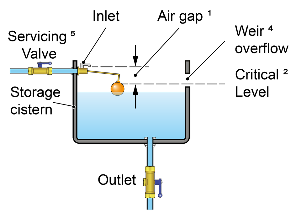
The air gap is an unobstructed and complete physical break between the lowest point of discharge and the critical water level of the weir overflow. Measured vertically it must be no less than 20 mm or twice the internal diameter of the supply whichever is the greater.
The critical level (sometimes referred to as h) is the fluid level in the receiving vessel under fault conditions i.e. when the outlet is closed but the inlet continues to discharge. It is measured at least 2 seconds after closing the water inlet
Whether sited internally or externally (as shown in the diagram opposite) the weir overflow must be rectangular (non-circular) and capable of accommodating discharge under fault conditions. Where a screened mesh is installed consideration should be given to the impact this may have on discharge flow.
The air gap can be confirmed by test or calculation using the Type AB air gap calculator.
Neither the fluid pathway to the overflow nor the discharge from it should be restricted. For example, there should be a sufficient gap between the overflow and any surface to accommodate full discharge unimpeded during fault conditions.
Submerged supply pipes are not permitted. If the supply pipe feeding the inlet or the inlet itself comes into contact with the contents of the receiving vessel, for example due to splashing or foaming, then the air gap is considered to be compromised and must be increased to the point no contact occurs.
Type AB air gap installations, including screened mesh, should be inspected, cleaned and as necessary maintained every 6 months (BS EN 806: 5)

To improve this information please give us your feedback >
Uncontrolled if downloaded. This is informative, non-statutory guidance and intended for general guidance purposes only; it is subject to change.
Compliance with this information should not be relied upon as guaranteeing no enforcement action will be taken by water undertakers. Water Regs UK accepts no liability for loss, indirect or consequential loss arising from or in connection with this guidance document.
A Type AC air gap is a non-mechanical backflow prevention arrangement comprising of a vented, but submerged inlet that discharges into a cistern, vessel, fitting or appliance fitted (receiving vessel) with an outlet and circular overflow.
A Type AC air gap is rated by the Regulators as suitable backflow protection against both back siphonage and back pressure for contamination risks no greater than fluid category 3 .
A summary of some of the key requirements applicable to a Type AC air gap is given below:
The air gap is an unobstructed and complete physical break between the lowest point of the vent (air inlet) and the critical water level of the weir overflow. It must be no less than 20 mm or twice the internal diameter of the supply whichever is the greater.
The critical level is the fluid level in the receiving vessel under fault conditions i.e. when the outlet is closed but the inlet continues to discharge. It is measured at least 2 seconds after closing the water inlet.
Supply pipes maybe submerged but adjustable or dismantlable joints on the are not permitted below the critical water level.
The overflow shall be not less than 19mm (internal diameter).
Where they discharge to drain the overflow and warning pipe must be fitted with an air break to drain or equivalent prior to the drain connection.
Type AC air gap installations should be inspected, and as necessary maintained every 12 months (BS EN 806: 5)
To improve this information please give us your feedback >
Uncontrolled if downloaded. This is informative, non-statutory guidance and intended for general guidance purposes only; it is subject to change.
Compliance with this information should not be relied upon as guaranteeing no enforcement action will be taken by water undertakers. Water Regs UK accepts no liability for loss, indirect or consequential loss arising from or in connection with this guidance document.
A Type AD air gap, sometime call a ‘jump jet’ is a non-mechanical backflow prevention arrangement comprising of a horizontal injector which ‘jets’ water into a cistern, vessel, fitting or appliance fitted (receiving vessel) and an air break to drain open to atmosphere.
A Type AD is rated by the Regulators as suitable backflow protection against both back siphonage and back pressure at the highest level of contamination risk, fluid category 5.
A summary of some of the key requirements applicable to a Type AD air gap is given below:
The air gap is an unobstructed and complete physical break between the terminal point of the injector and inlet orifice of the receiving vessel. Measured horizontally it must be no less than 20 mm or twice the internal diameter of the supply whichever is the greater.
The air break to drain must be open to atmosphere and capable of draining the maximum flow rate without submerging or coming into contact with the inlet.
The inlet must not come into contact with any splashing, drips or run off from the receiving vessel.
Type AD air gap installations should be inspected, and as necessary maintained every 6 months (BS EN 806: 5)
To improve this information please give us your feedback >
Uncontrolled if downloaded. This is informative, non-statutory guidance and intended for general guidance purposes only; it is subject to change.
Compliance with this information should not be relied upon as guaranteeing no enforcement action will be taken by water undertakers. Water Regs UK accepts no liability for loss, indirect or consequential loss arising from or in connection with this guidance document.
A Type AF air gap is a non-mechanical backflow prevention arrangement comprising of an inlet which discharges water into a cistern, vessel, fitting or appliance fitted (receiving vessel) fitted with an outlet and circular overflow.
A Type AF air gap is rated by the Regulators as suitable backflow protection against both back siphonage and back pressure for contamination risks no greater than fluid category 4.
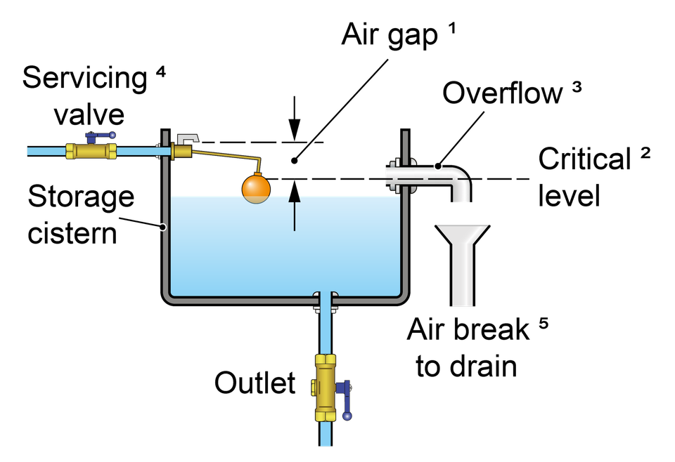
A summary of some of the key requirements applicable to a Type AF air gap is given below:
The air gap is an unobstructed and complete physical break measured downwards between the lowest point of discharge from the inlet and the critical water level. It must be no less than 20 mm or twice the internal diameter of the supply whichever is the greater.
The critical level is the fluid level in the receiving vessel under fault conditions i.e. when the outlet is closed but the inlet continues to discharge. It is measured at least 2 seconds after closing the water inlet
The overflow must be circular and of a minimum size throughout its length (four times in the inlet pipe cross sectional area). It must be capable of draining the maximum inflow of water under fault conditions i.e. when the outlet is closed but the inlet continues to discharge.
Submerged supply pipes are not permitted. If the supply pipe feeding the inlet or the inlet itself comes into contact with the contents of the receiving vessel, for example due to splashing or foaming, then the air gap is considered to be compromised and must be increased to the point no contact occurs.
Where they discharge to drain the overflow and warning pipe must be fitted with an air break to drain or equivalent prior to the drain connection.
Type AF air gap installations should be inspected, and as necessary maintained every 12 months (BS EN 806: 5)
To improve this information please give us your feedback >
Uncontrolled if downloaded. This is informative, non-statutory guidance and intended for general guidance purposes only; it is subject to change.
Compliance with this information should not be relied upon as guaranteeing no enforcement action will be taken by water undertakers. Water Regs UK accepts no liability for loss, indirect or consequential loss arising from or in connection with this guidance document.
A Type AG air gap is a non-mechanical backflow prevention arrangement comprising of an inlet which discharges water into a cistern, vessel, fitting or appliance fitted (receiving vessel) fitted with an outlet and minimum sized circular overflow.
A Type AG air gap is rated by the Regulators as suitable backflow protection against both back siphonage and back pressure for contamination risks no greater than fluid category 3.
A summary of some of the key requirements applicable to a Type AG air gap is given below:
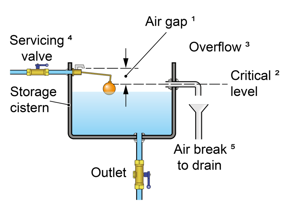
The air gap is an unobstructed and complete physical break measured downwards between the lowest point of discharge from the inlet and the critical water level. It must be no less than 20 mm or twice the internal diameter of the supply whichever is the greater.
The critical level is the fluid level in the receiving vessel under fault conditions i.e. when the outlet is closed but the inlet continues to discharge. It is measured at least 2 seconds after closing the water inlet
The overflow must be circular and a minimum of 19mm throughout its length. It must be capable of draining the maximum inflow of water under fault conditions i.e. when the outlet is closed but the inlet continues to discharge.
Supply pipes maybe submerged but adjustable or dismantlable joints on the are not permitted below the critical water level. If the inlet itself comes into contact with the contents of the receiving vessel, for example due to splashing or foaming, then the air gap is considered to be compromised and must be increased to the point no contact occurs.
Where they discharge to drain the overflow and warning pipe must be fitted with an air break to drain or equivalent prior to the drain connection.
Type AG air gap installations should be inspected, and as necessary maintained every 12 months (BS EN 806: 5)
To improve this information please give us your feedback >
Uncontrolled if downloaded. This is informative, non-statutory guidance and intended for general guidance purposes only; it is subject to change.
Compliance with this information should not be relied upon as guaranteeing no enforcement action will be taken by water undertakers. Water Regs UK accepts no liability for loss, indirect or consequential loss arising from or in connection with this guidance document.
A Type AUK1 air gap is a non-mechanical backflow prevention arrangement comprising of an interposed cistern fed via an inlet arrangement forming a Type AG air gap, and an outlet arrangement which discharges the contents by gravity into a separate receiving vessel. The receiving vessel (for example a WC pan or cistern) must be located a minimum distance below the interpose cistern. Depending on the outcome of an assessment by the local water undertaker can feed a single or multiple installations.
A Type AUK 1 air gap is rated by the Regulators as suitable backflow protection against back pressure risks no greater fluid category 3 and back siphonage risks up to and including fluid category 5.
A summary of some but not all of the requirements applicable to a Type AUK1 air gap is given below:
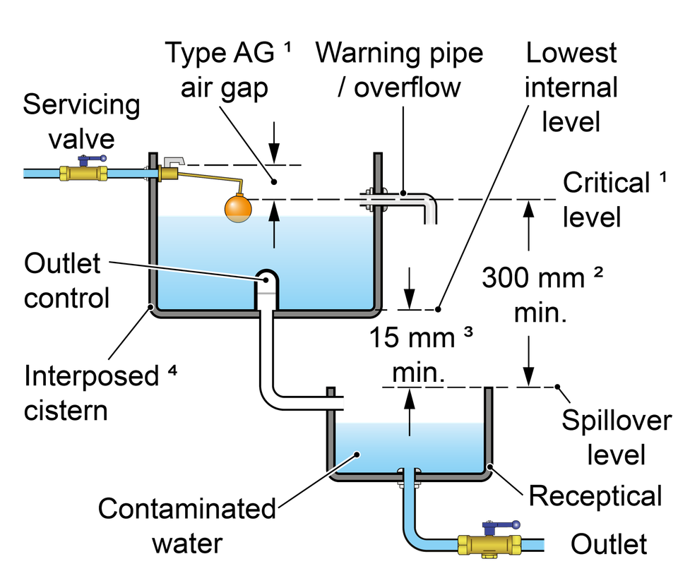
The interposed cistern must conform to the requirements for a Type AG air gap.
The maximum fluid level in the receiving vessel must be a minimum of 300 mm below the spillover level of the interposed cistern and invert (lowest point of flow which may be different to the lowest point of discharge) of the warning pipe.
The maximum fluid level in the receiving vessel must be a minimum of 15 mm below the lowest internal water level of the interposed cistern.
The fluid in the interposed cistern must be categorised as no greater than fluid category 3.
As it includes a Type AG air gap, Type AUK 1 installations should be inspected, and as necessary maintained every 12 months (BS EN 806: 5)
To improve this information please give us your feedback >
Uncontrolled if downloaded. This is informative, non-statutory guidance and intended for general guidance purposes only; it is subject to change.
Compliance with this information should not be relied upon as guaranteeing no enforcement action will be taken by water undertakers. Water Regs UK accepts no liability for loss, indirect or consequential loss arising from or in connection with this guidance document.
Type AUK 2 tap gap is suitable for low risk installations (no greater than fluid category 3). It is a specific minimum distance between the lowest point of a tap spout, shower head or other fitting and the spillover level of the low risk receptable it supplies.
A Type AUK 2 tap gap is rated by the Regulators as suitable backflow protection against contamination risks no greater than fluid category 3 but for back siphonage only.
The requirements for a Type AUK2 tap gap are:
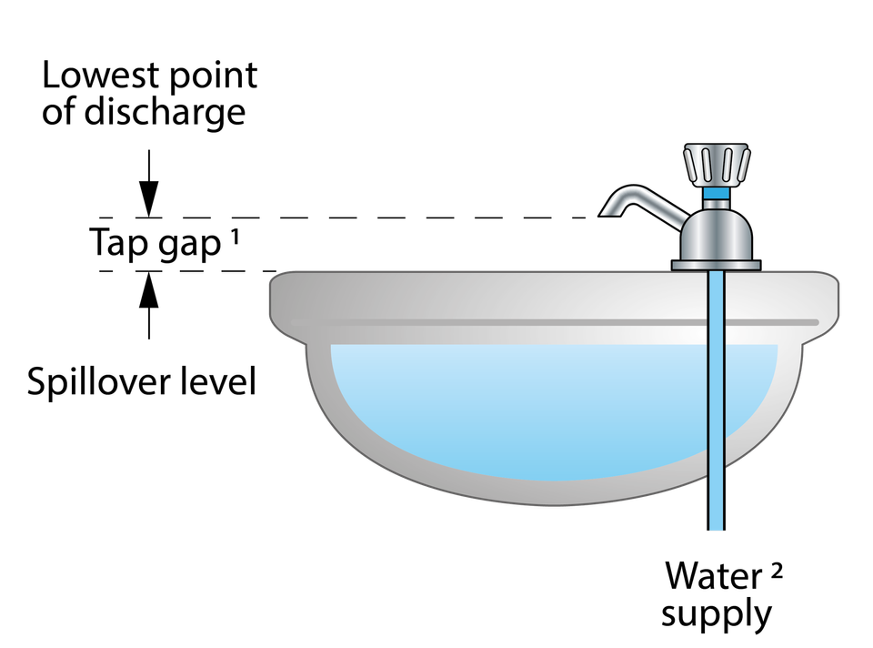
The tap gap is measured vertically from the lowest point of the outlet, which includes any aerator or flow straightener fitted, and the spillover level of whatever receptacle it supplies.
The gap required will vary depending upon the connection size of the tap or combination fitting as given below:
Connection size
Not exceeding ½“
Exceeding ½”but not exceeding ¾”
Exceeding ¾”
Tap gap
≥ 20 mm
≥ 25 mm
≥ 70 mm
To improve this information please give us your feedback >
Uncontrolled if downloaded. This is informative, non-statutory guidance and intended for general guidance purposes only; it is subject to change.
Compliance with this information should not be relied upon as guaranteeing no enforcement action will be taken by water undertakers. Water Regs UK accepts no liability for loss, indirect or consequential loss arising from or in connection with this guidance document.
A Type AUK 3 tap gap is suitable for high risk installations (fluid category 5 or lower). It is a specific minimum distance between the lowest point of a tap spout, shower head or other fitting and the spillover level of the high risk appliance or receptable it supplies.
A Type AUK 3 tap gap is rated by the Regulators as suitable backflow protection against the highest level of contamination, fluid category 5 but for back siphonage only.
The requirements for a Type AUK3 tap gap are :
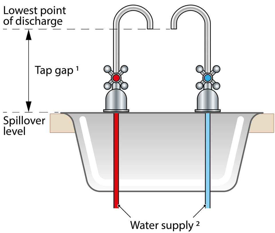
The tap gap is measured vertically from the lowest point of the outlet, which includes any aerator or flow straightener fitted, and the spillover level of whatever receptacle it supplies.
The gap required must be not less than 20 mm or twice the diameter of the inlet pipe supplying the installation whichever is the greater.
Where an AUK3 tap gap cannot be maintained, for example where the tap gap is compromised as a result of:-
the tap being lowered in any way;
adjustment to the spout which reduces the distance between the tap outlet and spillover level of the sink; or
the operation of a pull out hose attachment
An alternative form of fluid category 5 backflow protection is required.
To improve this information please give us your feedback >
Uncontrolled if downloaded. This is informative, non-statutory guidance and intended for general guidance purposes only; it is subject to change.
Compliance with this information should not be relied upon as guaranteeing no enforcement action will be taken by water undertakers. Water Regs UK accepts no liability for loss, indirect or consequential loss arising from or in connection with this guidance document.
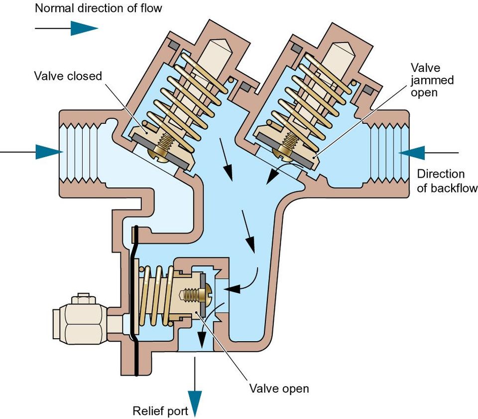
A Type BA, more commonly known as a reduced pressure zone or RPZ valve, is a mechanical backflow protection device. It comprises of a combination of check and relief valves in different zones which perform specific functions to ensure there is no backflow should the downstream pressure become higher than the incoming supply or the valve malfunctions.
An RPZ valve is rated by the Regulators as suitable backflow protection against both back siphonage and back pressure for contamination risks no greater than fluid category 4 .
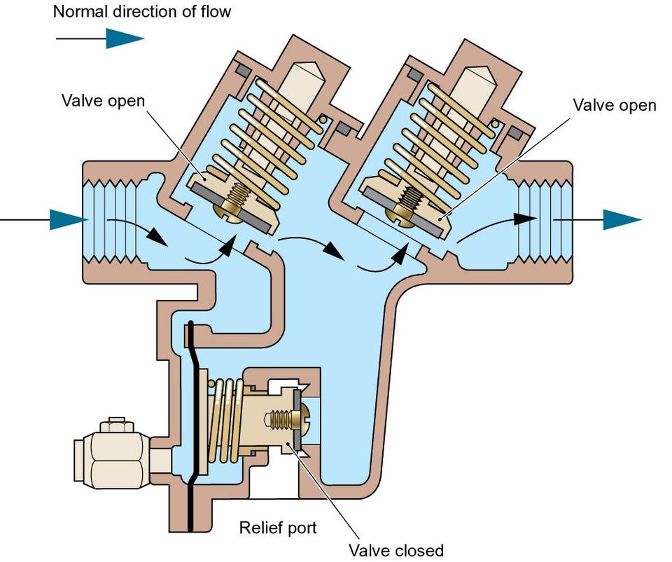
In addition to regular inspection RPZ valves are required to undergo routine testing to verify they are working correctly. For further information about this testing as well as specific installation requirements please refer to the RPZ AIM and FAQs. Please note testing intervals will be at the discretion of the local water undertaker but not less than annually.
To improve this information please give us your feedback >
Uncontrolled if downloaded. This is informative, non-statutory guidance and intended for general guidance purposes only; it is subject to change.
Compliance with this information should not be relied upon as guaranteeing no enforcement action will be taken by water undertakers. Water Regs UK accepts no liability for loss, indirect or consequential loss arising from or in connection with this guidance document.
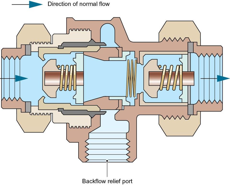
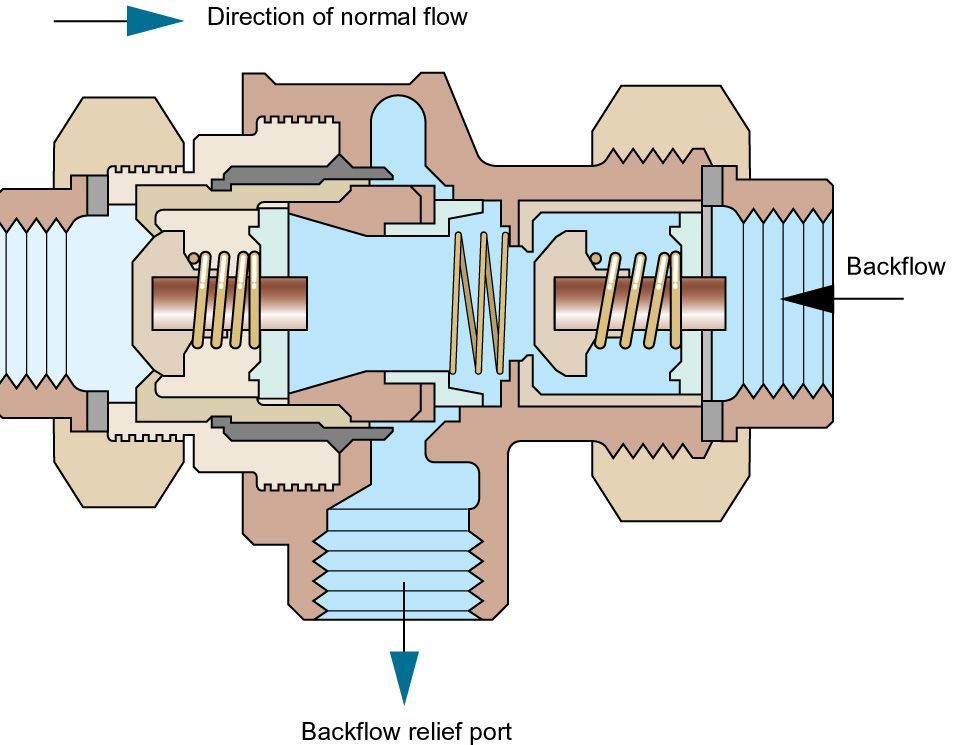
A Type CA device is a mechanical backflow protection device. It comprises of a combination of check valves and a relief port. A disconnection is created as a result of the relief valve venting when the pressure differential across the check valves falls below 10% of the upstream pressure.
Type CA devices are rated by the Regulators as suitable backflow protection against both back siphonage and back pressure for contamination risks no greater than fluid category 3.
Type CA devices should be inspected every 6 months and as necessary maintained every 12 months (BS EN 806: 5)
To improve this information please give us your feedback >
Uncontrolled if downloaded. This is informative, non-statutory guidance and intended for general guidance purposes only; it is subject to change.
Compliance with this information should not be relied upon as guaranteeing no enforcement action will be taken by water undertakers. Water Regs UK accepts no liability for loss, indirect or consequential loss arising from or in connection with this guidance document.
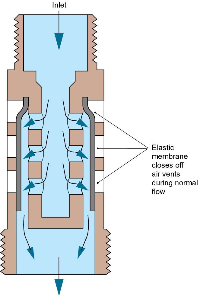
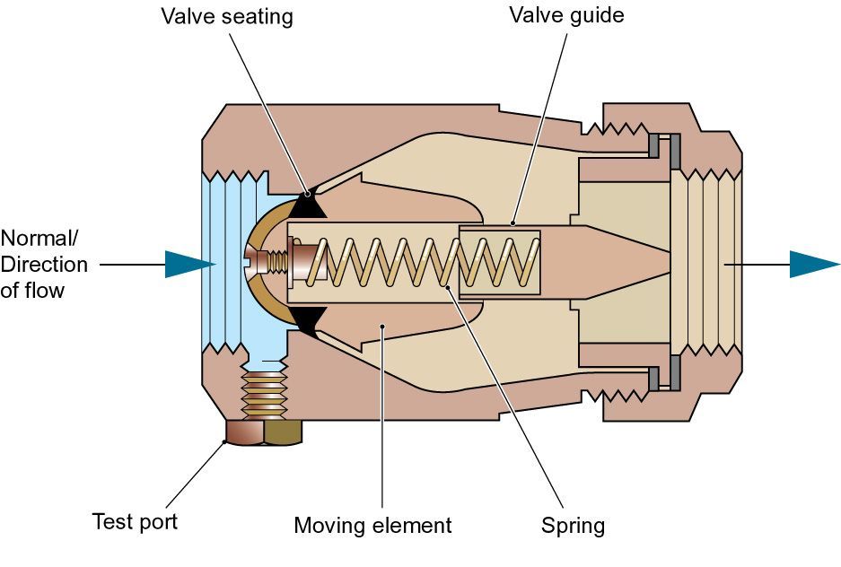
A Type DB arrangement comprises of a pipe interrupter with a moving element (Type DB device) fitted not less than 300 mm above the spillover of any appliance or receiving vessel it supplies, discharging vertically downwards to an open outlet i.e. no method of flow control.
A Type DB arrangement is rated by the Regulators as suitable backflow protection against contamination risks no greater than fluid category 4 but for back siphonage only.
Type DB arrangements should be inspected and as necessary maintained every 12 months (BS EN 806: 5)
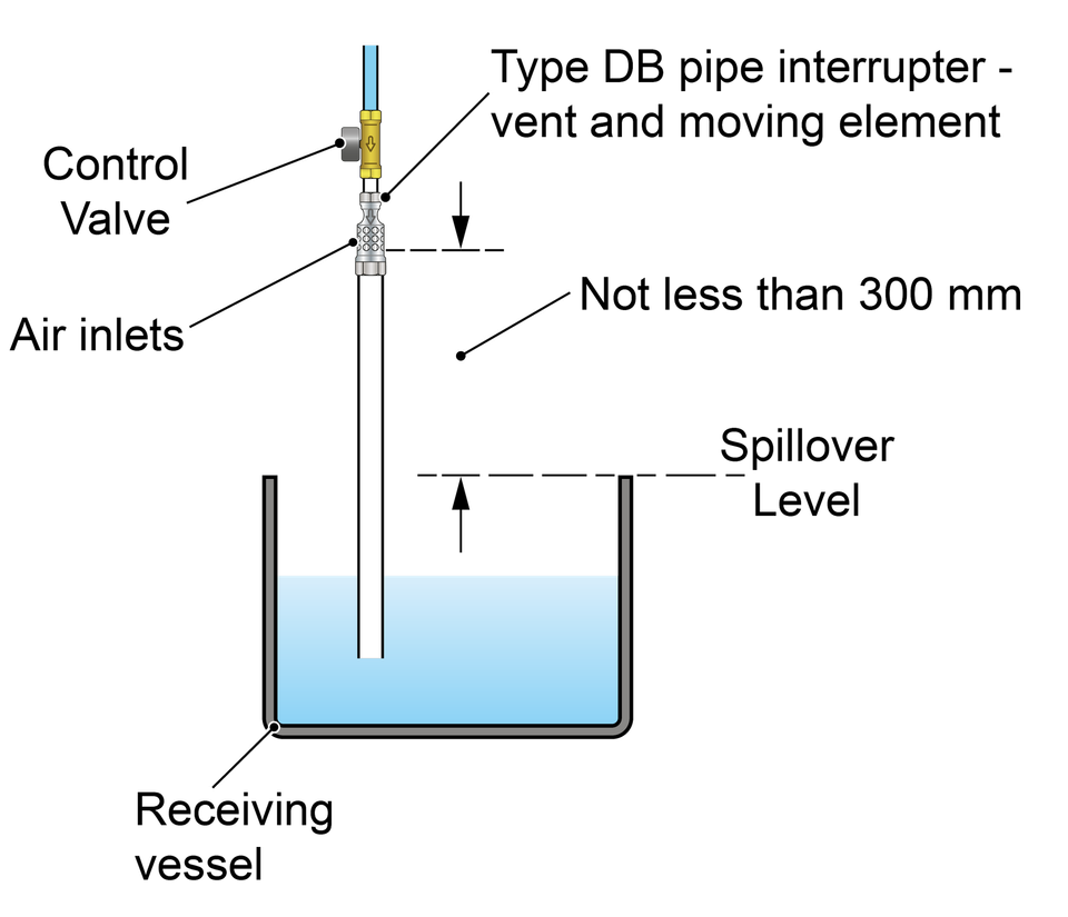
A DB device incorporates a moving element which closes the air inlets when the device is in use but opens to allow air if the upstream water pressure falls to atmospheric pressure.

To improve this information please give us your feedback >
Uncontrolled if downloaded. This is informative, non-statutory guidance and intended for general guidance purposes only; it is subject to change.
Compliance with this information should not be relied upon as guaranteeing no enforcement action will be taken by water undertakers. Water Regs UK accepts no liability for loss, indirect or consequential loss arising from or in connection with this guidance document.
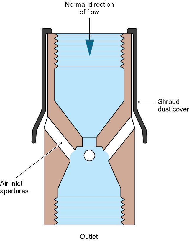
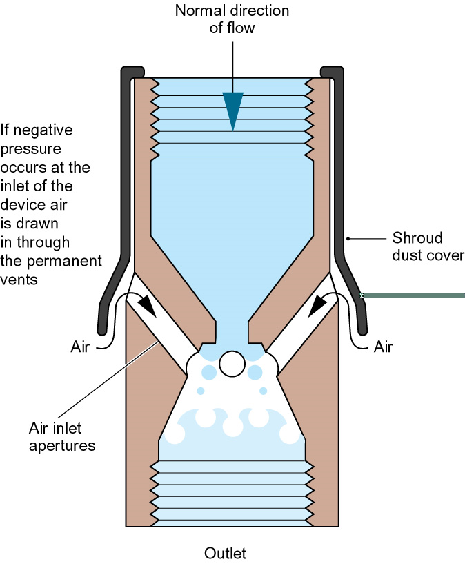
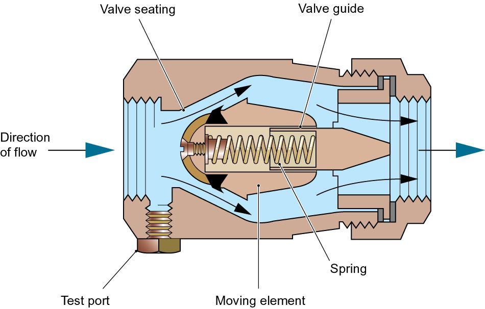
A Type DC arrangement comprises of a pipe interrupter with shrouded, permanently unrestricted air inlets (Type DC device) installed not less than 150 mm above the sparge outlet of a urinal or 300 mm (150 mm In Scotland) above the spillover of a WC pan or any other receiving vessel, discharging vertically downwards to an open outlet i.e. no method of flow control.
A Type DC arrangement is rated by the Regulators as suitable backflow protection against the highest level of contamination, fluid category 5 but for back siphonage only.
Type DC arrangement should be inspected, and as necessary maintained every 6 months (BS EN 806: 5)
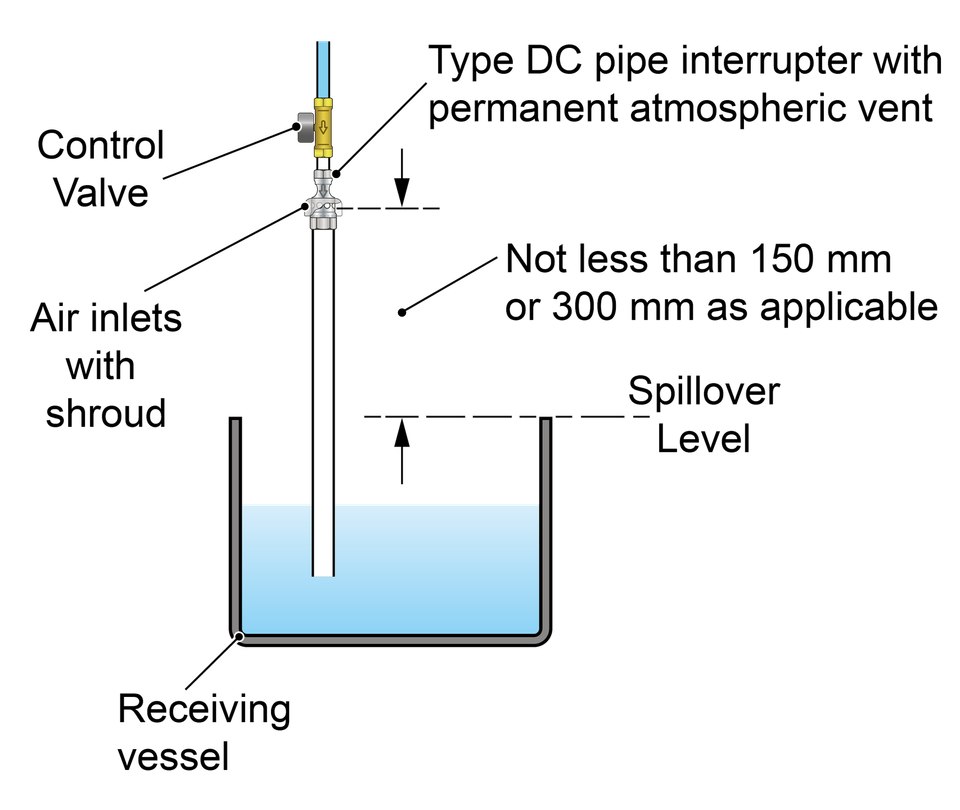
Type DC device
To improve this information please give us your feedback >
Uncontrolled if downloaded. This is informative, non-statutory guidance and intended for general guidance purposes only; it is subject to change.
Compliance with this information should not be relied upon as guaranteeing no enforcement action will be taken by water undertakers. Water Regs UK accepts no liability for loss, indirect or consequential loss arising from or in connection with this guidance document.
A single check valve is a mechanical backflow protection device. It permits water to flow from upstream to downstream but not in the reverse direction.
A single check valve is rated by the Regulators as suitable backflow protection against both back siphonage and back pressure for contamination risks no greater than fluid category 2.
Single check valves should be inspected and maintained every 12 months: non-verifiable single check valves should be replaced every 10 years (BS EN 806: 5).
There are two ways to verify the backflow protection capabilities of single check valves, both rely on satisfying a specification including performance testing. These are:
Conformity with BS EN 13959, the British Standard for both single and double checks valves, this also includes provision for fittings incorporating these devices (or equivalent).
or
Conformity with all of the tests from the Regulators Specification for fittings applicable to devices intended to be used as a single or double check valve.
To improve this information please give us your feedback >
Uncontrolled if downloaded. This is informative, non-statutory guidance and intended for general guidance purposes only; it is subject to change.
Compliance with this information should not be relied upon as guaranteeing no enforcement action will be taken by water undertakers. Water Regs UK accepts no liability for loss, indirect or consequential loss arising from or in connection with this guidance document.
A double check valve is a mechanical backflow protection device. Comprising of two single check valves in series, a double check valve permits water to flow from upstream to downstream but not in the reverse direction.
A double check valve is rated by the Regulators as suitable backflow protection against both back siphonage and back pressure for contamination risks no greater than fluid category 3.
Double check valves should be inspected and maintained every 12 months: non-verifiable double check valves should be replaced every 10 years (BS EN 806: 5).
There are two ways to verify the backflow protection capabilities of a double check valve, both rely on satisfying a specification including performance testing. These are:
Conformity with BS EN 13959, the British Standard for both single and double checks valves, this also includes provision for fittings incorporating these devices (or equivalent).
or
Conformity with all of the tests from the Regulators Specification for fittings applicable to devices intended to be used as a single or double check valve.
To improve this information please give us your feedback >
Uncontrolled if downloaded. This is informative, non-statutory guidance and intended for general guidance purposes only; it is subject to change.
Compliance with this information should not be relied upon as guaranteeing no enforcement action will be taken by water undertakers. Water Regs UK accepts no liability for loss, indirect or consequential loss arising from or in connection with this guidance document.
Irrespective of what a device is called, for the purposes of the water fittings regulations, byelaws in Scotland, the important factor is whether it provides protection against backflow.
There are two ways to verify the backflow protection capabilities of a device, both rely on satisfying a specification including performance testing. These are:
Conformity with BS EN 13959, the British Standard for both single and double checks valves, this also includes provision for fittings incorporating these devices.
or
Conformity with all of the tests from the Regulators Specification for fittings applicable to devices intended to be used as a single or double check valve.
Both of these routes include endurance tests intended to demonstrate the device continues to operate correctly over its lifetime.
Example of a non-return valve
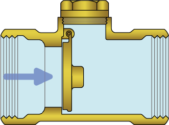
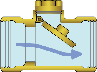
Example of a check valve
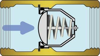

The terms ‘check valve’ and ‘non-return’ valve are both commonly used to describe a device which allows flow from upstream to downstream but not the reverse. Only valves, or fittings incorporating devices, which conform with one of the above specifications can claim to provide backflow protection.
Those meeting the requirements of a single check valve can be used for fluid category 2 backflow protection, whereas those satisfying the requirements for a double check valve can be used for up to fluid category 3 backflow protection.
To improve this information please give us your feedback >
Uncontrolled if downloaded. This is informative, non-statutory guidance and intended for general guidance purposes only; it is subject to change.
Compliance with this information should not be relied upon as guaranteeing no enforcement action will be taken by water undertakers. Water Regs UK accepts no liability for loss, indirect or consequential loss arising from or in connection with this guidance document.
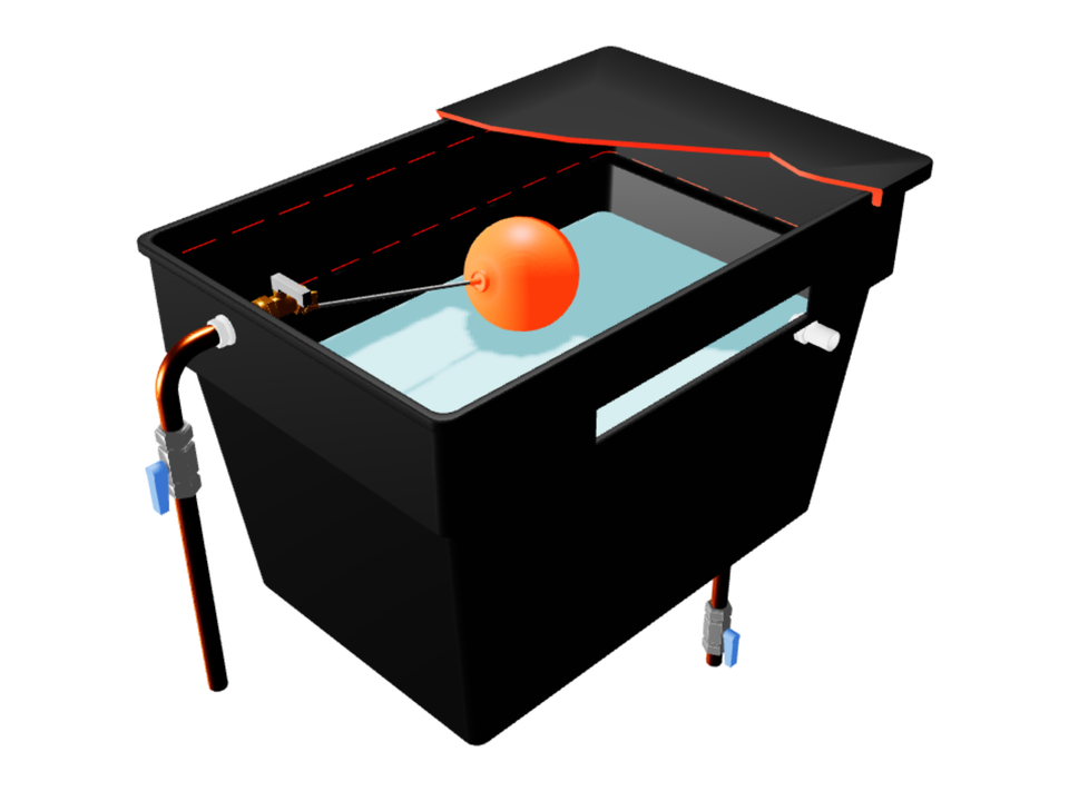
To be considered as providing fluid category 5 backflow protection, in addition to maintaining a suitable air gap, the water pathway to a Type AB air gap overflow, and discharge from the weir itself, must be unrestricted.
If the overflow is located close to another surface, such as a wall or other installation behind, in front or below the overflow, the gap between the discharge point and these surfaces must be sufficient to accommodate full discharge unimpeded. One way to demonstrate this is to ensure there is a clearance equivalent in shape and size to the weir overflow which is maintained to the air break to drain or floor level.
To improve this information please give us your feedback >
Uncontrolled if downloaded. This is informative, non-statutory guidance and intended for general guidance purposes only; it is subject to change.
Compliance with this information should not be relied upon as guaranteeing no enforcement action will be taken by water undertakers. Water Regs UK accepts no liability for loss, indirect or consequential loss arising from or in connection with this guidance document.
We use cookies to give you the best possible experience with Water Regs UK. Some are essential to provide website functions and ensure the website is secure. We also use cookies to help us understand how people use the site and to make improvements. Click "Accept All" to enable recommended settings or click "Manage cookies" to adjust your settings. For more details, see our Cookie Policy.